Technical index

TECHNICAL DEFINITIONS

Standards, powers, windings, transformers, autotransformers, find all the answers to the main technical questions you ask yourself.

CHOOSING A TRANSFORMER

A transformer is an integral part of any electrical system. It ensures its safety and the perfect fit when needed.

Choosing a transformer is an important decision to ensure the right performance of your applications. For this, the following technical characteristics must be determined.

  • Current (single or three-phase)
  • Power(en VA ou kVA)
  • Primary voltage (input)
  • Secondary voltage (output)
  • Use (determines the appropriate standard and protection rating)
  • Protection rating (IP00 or enclosure)
  • Accessories and options (rolling bears, thermal sensors, vibratio-isolating mount, electrostatic shield, regulation tabs) 

INDEX

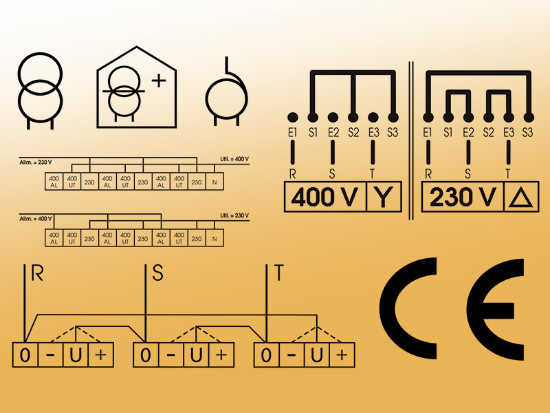
General informations

  • EN 61558-2-1 Low capacity power insulation transformers
  • EN 60076 Power transformers or autotransformers  (< 1 000 VA single phase ; < 5 000 VA three phase)
  • EN 61558-2-2 Control transformers
  • EN 61558-2-4 Isolating transformers
  • EN 61558-2-6 Safety isolating transformers
  • EN 61558-2-13 Low capacity power autotransformers
  • EN 61558-2-15 Isolating transformers for medical usages
  • EN 61558-2-20 Inductors
  • EN 60947-4-1 Start-up autotransformers three phase motor
  • UL5085-1 & CSA 22.2 Transformers for USA and Canada

Indicated levels are for power in VA or kVA, it is the product of the secondary rated voltage by the nominal intensity for single phase devices, and √3 for three phase as devices.

All our windings are made with wire or enamel varnish flat wire F or H class. The insulation used between layers or turns follows NFC 26-206 or CEI 60085 standards:
  • B    Maximum temperature 130°C
  • F    Maximum temperature 155°C
  • H   Maximum temperature 180°C

Depending upon their power or their characteristics, magnetic circuits are made :

  • Silicon electrical steel (1,7 W)
  • Grain oriented silicon steel (0,6 W)

All our equipment is systematicaly impregnated with an H class varnish, either the complete transformer :

  • To avoid moisture absorption ,
  • To stop wear due to vibration,
  • To improve thermal exchange,
  • To reduce noise level.

On request, we also apply a special treatment for extreme environments. On top of a complete treatment by impregnation, we add one overall coat of “anti flash” varnish. The last coat improves resistance to moisture, mushrooms and all conductive dusts.

Our equipments follow IEC 61140 standard requirements:
  • Classe 0
  • Classe I (with earthing terminal)
  • Classe II (on request)
For the enclosed type transformer, the equipment is protected by a metallic enclosure as per EN 60529 and EN 62262 standards:
  • IP21 – IK08 (except the bottom)
  • IP54 – IK08
  • Other on request
Incoming and outgoing connections can be made through the bottom section or the top.
Gloss paint – colour RAL 7035, other on request.
An electrostatic screen made of copper sheet or brass is inserted between the primary and secondary windings. It forms an open coil and is usually earthed to the metallic body of the device.
It has 2 main functions:
  • Supplementary insulation : in this case, it acts like a barrier for a primary insulation fault and carries the fault to earth without affectif the secondary side.
  • Reduction of static noise : if used as a computer supply, it carries part of the network static noise to earth.
  • An autotransformer has only one winding rated for the highest voltage. The lowest voltage is obtained on the middle tap changer.
  • Therefore, there is no insulation between circuits and use of this type of transformer must not be used as a safety transformer or to achieve circuit separation. However, the transformer is a very economical solution to obtain a voltage change. (Ex: a 10 000VA autotransformer will be the same size and losses as a 4 000VA transformer).
  • Our AMS and ATS autotransformers are equiped with a compensation tab to insure a real reversibility in use.
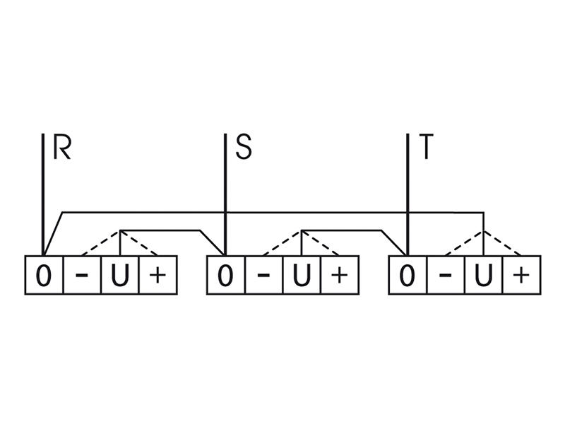
  • The sizing of an artificial neutral is directly connected to the network voltage and to the necessary intensity in the neutral. The winding is crossed only by this intensity. The power absorbed on the network does not intervene.
  • The divisor of tension is used to create a neutral on a three-phase network. It does not change the value of the network voltage.
    WARNING, with the divisor, we do not realize change of regime of the neutral, for it is necessarily needed a transformer.
  • All our equipment and winding characteristics are systematically tested. On request, we can provide a test report to the customer.
  • All the materials used and the process to be operated are reported on a manufacturing file which follows the product throughout its realization. This file is infinitely preserved in paper and computer versions. The electrical specifications recorded can be the object of a trial report to be asked with order.

Transformers operation

  • The windings followed by an electric current give off an amout of heat which is proportional to their resistance and to the square of the current going through them. This is the JOULE effect or also referred to as “load losses”. The presence of harmonic currents not apprenhended on the production calculations may considerably increase this phenomena.
  • The magnetisation of the plates results in heat being given off due to two sorts of loss: losses by hysteresis and FOUCAULT current losses ; these are grouped together under the name “iron losses” and are independent of the load. That is to say that when powered under no-load, the magnetic circuit of a transformer heats up. Here again, the presence of harmonic currents or the appliances power supply being by a non-sinusoidal signal (driven by thyristor, rectification, variator,…) may considerably aggravate the level of these losses and thus that of the temperature.
  • The user should take into account the addition of load losses and iron losses also called no load losses in dimensioning the cabinet, for example.
  • The temperatures reached by the windings and the magnetic circuits are described and limited depending on the insulation class used and by the various standards used for the production of the transformers. As an example, C 26-206 or IEC 85 called “assessment and thermal CERTIFICATION of electrical insulation” sets the maximum windings temperatures for each insulation class as below :
    • A Class : 105°C
    • E Class : 120°C
    • B Class : 130°C }maximum windings temperatures
    • F Class : 155°C
    • H Class : 180°C
These temperatures are normal and have no consequences on the various materials used in the producing the appliances when they are chosen accordingly.

Circuit vibration is due to the movement of the magnetic field in the plates. It is this variation which generates the perceptible noise. However, the transformer is an industrial element designed to work in an industrial noise environment. The manufacturing standards do not state a limit : they are subject to agreement with user.

  • The value of the winding leakage inductance, which creates the inductive voltage drop, and the value of the resistance of the windings, which creates the resistive voltage drop, combine to create the transformer’s voltage drop. This parameter varies according to the load applied.
  • For the voltage under load to be correct, the manufacturer should take this drop into account in its calculations. A no-load voltage greater than the voltage under load of the secondary winding is the consequence of this phenomena. Limits are provied in certain standards.
  • Using a transformer of a rating much greater in use may lead to obtaining a voltage under load which is too great, especially in the small ratings. This voltage under load is increased more if the supply voltage is greater than the nominal voltage.
  • The manufacturing standards for transformers impose the electrical and environmental specifications which are used to define the appliances we offer.
The parameters provided for nearly always envisage :
  • A fixed nominal voltage which is disturbance-free.
  • Usage at nominal power at a cos φ of 0,8 to 1,0.
  • An ambiant temperature which does not exceed that indicated on the identificatin plate (35°C by défault).
  • Standard hygrometric conditions.
  • Height less than 1 000 m

Thermal sensors

They are bimetallic elements, composed with 2 blades of alloys such as the temperature rise cuts (probe with opening) or restores (probe with lock) the contact connection. Their shutdown capicity is 250V – 2,5A in alterneting..

They are metallic resistance sensors type. The PT100 sensor is in platinum and have a resistance of 100 at 0°C. The sensor resistivity will increase with the temperature. It must be linked with a converter which cannot be installed in the transformer enclosure. Indeed, the temperature in the enclose borders 70 / 90°C and is incompatible with the smooth running of the converter. This sensor allows the continuous display of the temperature.

They belong to the range of thermistors. They are resistances with metallic oxides. The PTC is a thermistor in coefficient of positive temperature, its resistance quickly increases from a certain temperature. It must be linked with a converter which cannot be installed in the transformer enclosure. Indeed, the temperature in the enclose borders 70 / 90°C and is incompatible with the smooth running of the converter.

Transformers protection

When energezing, the transformer inrush current is approximately 7 – 25 ln. The short circuit protection must be properly calibrated to take this inrush current into account.
2 possibilities:
  • aM fuse type calibrated in accordance with transformer inrush current.
  • Breaker with magnetic trip adjusted according to manufacturer recommandations.
Secondary side protection must take care of overload and short circuit on the user side.
3 possibilities:
  • Miniature fuses follows IEC 60127.
  • gG fuse type
  • Type C magnetic breaker with thermal unit.
EN 61558-1 standard indicates that : “During normal use, the transformer should not become dangerous in the event of short circuit of overload”. It also requires the manufacturer to indicate on the equipment name plate the size and location of the protection fuse. In order to satisfy this particular requirement, the transformers must pass an overload test determined by a K factor and the protection size.
This objectif of this standard is to improve transformer safety and reliability. However, in most cases, it requires the manufacturer to oversize the equipment.
Example :
  • Single phase transformer 250VA 230 V / 24V
  • ln = 250 / 24 = 10,41 A
  • Fuse size : 10 A gG cartridge
  • Overload intensity : 10 A x 1,9 = 19 A for one hour
    (Overload coefficient K=1,9 and test time defined by standard).
  • Overload power : 19 A x 24V = 456 VA equals 80% of the overload.

IP00 : No protection
IP20 : Protection against foreign solid bodies Ø > 12,5 mm
Protection against foreign solid bodies Ø > 12,5 mm and vertical water drops
IP23 : Protection against foreign solid bodies Ø > 12,5 mm and 60° rain
IP31 : Protection against foreign solid bodies Ø > 2,5 mm and vertical water drops
IP41 : Protection against foreign solid bodies Ø > 1 mm and rain
IP54 : Protection against dust and water spray
IP65 : Any direction full protection against dust and hose water jets

Electrical wiring instructions

  • EUR and EURM type transformers 2 x 24V and 2 x 115V are double voltage (24 or 48 V and 115 or 230 V) by serial or parallel coupling.
  • The lower voltage (24V and 115V) is obtained by realizing the parallel coupling by connecting together E1 and E2 terminals and S1 and S2.
  • The highest voltage is obtained by realizing a serial coupling by connecting E2 and S1 terminals.
  • In every case, the secondary terminals are E1 and S2. The obtained power is equal to the rated output.
  • Usually, our three phase transformers are connected according to delta coupling on primary side. With the input voltage tabs, the user should realize delta coupling is as left.
  • Connect to make “V” between terminals “0” and terminals “+” or “U” or “-” according to the real values (0/-5% / 400 V/+5% for example)

In some case, input voltage can be choiced (230 V or 400 V for example) according to the coupling.
If you want 400 V, you make a star coupling, if you want 230 V you make a delta coupling.

  • Our three phase autotransformers are reversible, input voltage can be 230 V and ouput 400 V or vice versa. So, there are two possibilities of connexion, see below.
  • Input voltage 230 V : the alimentation three phase have to be connected on terminals “230” and the using three phase have to be connected on terminals “400” UT.
  • Input voltage 400 V : the alimentation three phase have to be connected on terminals “400 AL” and the using three phase have to be connected on terminals “230”.

A REQUEST FOR INFORMATION ?

Our team is at your disposal to support you in all your projects.
Please contact us for any information request.

contact us